
• T 704 529 5442 W pattonsmedical.com
Page 1
DOC# Manual_Signal1 Revision 11/1/2021
SIGNAL 1 with SYSTEM HEALTH
OPERATING INSTRUCTIONS
SIGNAL 1 with SYSTEM HEALTH
OPERATING INSTRUCTIONS
• Medical Air
• Lab Air
• Instrument Air
• Medical Vacuum
• Lab Vacuum
Signal 1
Operation and
Maintenance
Manual

• T 704 529 5442 W pattonsmedical.com
Page 2
DOC# Manual_Signal1 Revision 11/1/2021
SIGNAL 1 with SYSTEM HEALTH
OPERATING INSTRUCTIONS
Table of Contents
• Contact Information
• Safety Precautions
• Control Panel Front
• Main Display Screen
• Menu Screen
• System Health Screen
• System Health Parameter
Adjustment screen
• Alarm History
• Pressure/Vac Settings
• System Data
• Common Alarms
• Service Intervals
• Service
• Troubleshooting
• Ambient Temp Trend
• Amps Trend
• Pressure/Vac Trend
• # Pumps Running Trend
• Pump Cycle TrendDew Point
Trend
• CO Trend
• LAN Settings
• HMI Settings Tab (Time/Date
change)
• Warranty

• T 704 529 5442 W pattonsmedical.com
Page 3
DOC# Manual_Signal1 Revision 11/1/2021
SIGNAL 1 with SYSTEM HEALTH
OPERATING INSTRUCTIONS
ADDRESS:
Pattons Medical LLC
4610 Entrance Drive, Suite H
Charlotte, NC 28273
PHONE:
704-529-5442
Service: X10250
Parts: X10248 or X10310
WEBSITE:
www.pattonsmedical.com

• T 704 529 5442 W pattonsmedical.com
Page 4
DOC# Manual_Signal1 Revision 11/1/2021
SIGNAL 1 with SYSTEM HEALTH
OPERATING INSTRUCTIONS
Pressurized air and vacuum from the system may cause personnel injury or property damage
if the unit is improperly operated or maintained. The operator should have carefully read and
become familiar with the contents of this manual before installing, wiring, starting, operating,
adjusting, and maintaining the system. The operator is expected to use common sense safety
precautions, good workmanship practices and follow any related local safety precautions.
• Safety Precautions
In Addition:
• Before starting any installation or maintenance procedures, disconnect all power to the
package.
• All electrical procedures must be in compliance with all national, state, and local codes and
requirements.
• A certified electrician should connect all wiring
• Refer to the electrical wiring diagram provided with the unit before starting any installation or
maintenance work.
• Release all pressure/vacuum from the package before removing, loosening, or servicing
any covers, guards, fittings, connections, or other devices.
• Notify appropriate hospital personnel if repairs or maintenance will affect available
compressed air/vacuum levels.
• AIR: Air inlet must be placed in an area free of toxic or hazardous contaminants. It must be
kept away from ETO exhaust vents, vacuum exhaust vents, areas close to automotive
exhausts, etc., in accordance with the latest edition of NFPA 99.
• Prior to using the medical system, the facility must have a certifier perform all installation
test as specified in the latest edition of NFPA 99 and is responsible for ensuring that the
Air/Vacuum meets the minimum requirements as specified in the latest edition of NFPA 99.
• This is a high speed, rotating piece of machinery. Do not attempt to service any part while
machine is in operation.
• Do not operate unit without safety devices (belt guards, shields, screens, etc.) in place.
• Make sure that all loose articles, packing material, and tools are clear of the package.
• Check all safety devices periodically for proper operation.
• AIR: Never operate a compressor with its isolation (shutoff) valve closed or without its relief
valve in place. Damage to the compressor may occur.
• Check compressor/vacuum requirements to see if oil is necessary for operation.
• The “HAND” mode of operation should only be used for emergencies such as PLC
malfunction and should not be used for normal operation.
• Electrical service must be the same as specified on the control panel nameplate or damage
to the equipment may occur.
• Vibration during shipment and operation can loosen electrical terminals, fuse inserts, and
mechanical connections. Tighten as necessary.
• Refer to the electrical diagram provided with the unit before starting any installation or
performing any maintenance work.
• Do not operate on a voltage other than the voltage specified on the system nameplate.
• All customer wiring should be in compliance with the National Electrical Code and any other
applicable state or local codes.
• T 704 529 5442 W pattonsmedical.com
Page 5
DOC# Manual_Signal1 Revision 11/1/2021
SIGNAL 1 with SYSTEM HEALTH
OPERATING INSTRUCTIONS
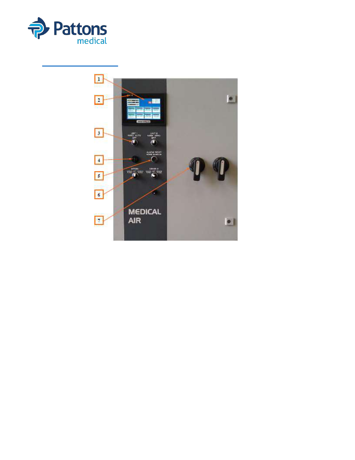
• Control Panel
1. Display Screen - Displays the systems operating screens.
2. LED’s – Yellow: Power is correctly supplied to the HMI Screen
3. HOA Selector Switch – Motor control switch, Hand – Off – Auto
4. Alarm Horn – Sounds when an alarm condition occurs
5. Alarm Reset/Horn Silence – Pushbutton to silence alarm and reset visual alarm on
Signal 1 screen after alarm condition is corrected
6. Dryer Control Selector Switch (Air) – Manual Purge – Off – Demand Purge
Purge Control Selector Switch (Vacuum) – Hand – Off – Auto Purge
7. External Operator – To control circuit breaker disconnect
• T 704 529 5442 W pattonsmedical.com
Page 6
DOC# Manual_Signal1 Revision 11/1/2021
SIGNAL 1 with SYSTEM HEALTH
OPERATING INSTRUCTIONS
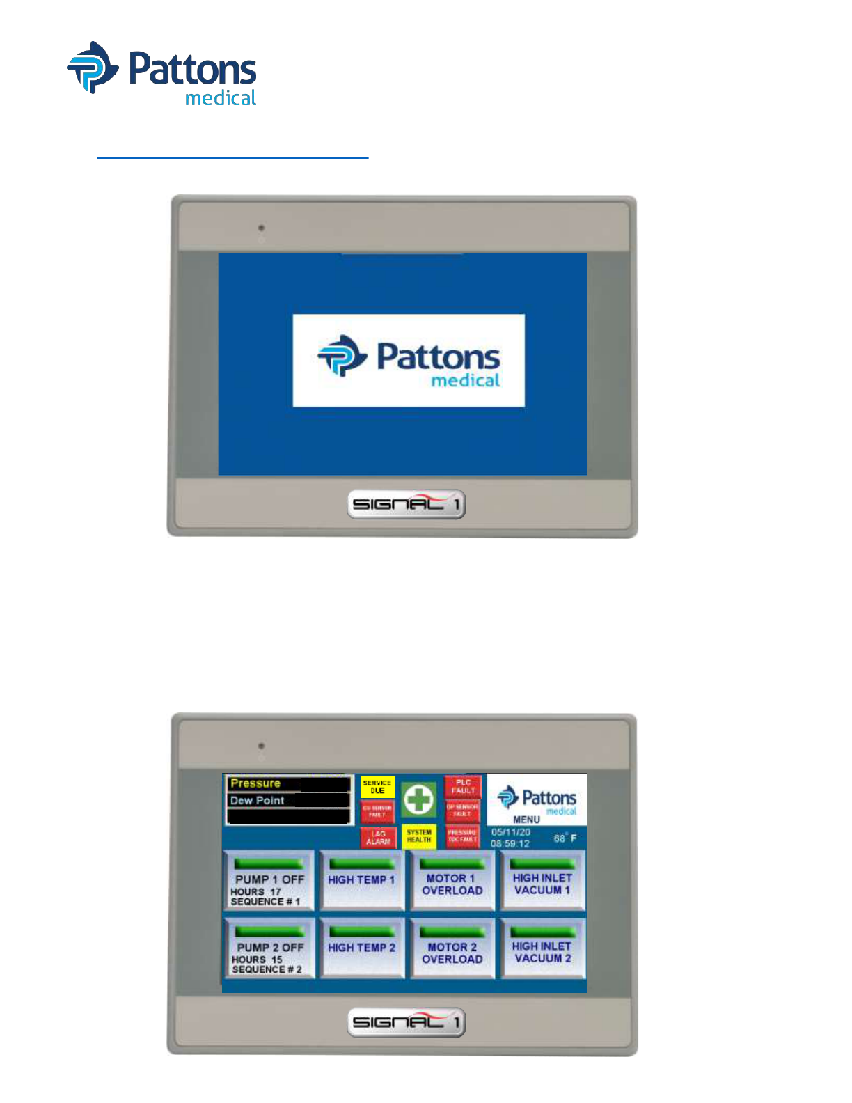
• Main Display Screen
At startup, you may get this screen. Touch the logo to proceed to the main screen.
95 PSI
-15 °C
CO 0 PPM
The main screen for systems will monitor and display the status of the system.
AIR: Receiver pressure, Dewpoint, CO, run sequence, hours, and current status of each module.
VACUUM: Receiver vacuum, run sequence, hours, and current status of each module.
Alarms for pressure/vacuum transducer fault, dewpoint sensor fault, CO sensor fault, PLC fault,
System Health warning, LAG Alarm, and service due also blink on this screen when activated.
Module alarms for high temperature, overload, and inlet vacuum (scroll only) will also blink when
Activated. Touching the icon of any alarm will take you to an informative screen.
The Menu screen in the upper right corner will allow you to navigate through multiple screens.

• T 704 529 5442 W pattonsmedical.com
Page 7
DOC# Manual_Signal1 Revision 11/1/2021
SIGNAL 1 with SYSTEM HEALTH
OPERATING INSTRUCTIONS
1. MENU: Displays menu screen which allows the operator to access the System Health
status, operating history, service requirements, trends, troubleshooting information,
pressure/vacuum settings, and system data information.
2. DEWPOINT (DP): Displays the current dew point reading at the units discharge point. If
the dew point reading is higher than 2°C, a high dew point alarm will occur. The dew point
indicatory will flash RED and the horn will sound. Pressing the RESET button on the
control panel front will silence the alarm. Touching the indicator while flashing red will open
a troubleshooting window. The dew point indicator will continue to flash red until the dew
point falls below 2°C. At this point, the dew point alarm will reset.
3. CARBON MONOXIDE (CO): Displays the current CO reading at the units discharge point.
If the CO reading is higher than 10 ppm, a high CO alarm will occur. The CO indicator will
flash RED and the horn will sound. Pressing the RESET button on the control panel front
will silence the alarm. Touching the indicator while flashing will open a troubleshooting
window. The CO indictator will continue to flash red until the CO falls below 10 ppm. At this
point, the CO alarm will reset.
4. PRESSURE (PSI): Displays the current pressure inside the receiver. Can change to BAR.
5. SERVICE DUE: Service intervals and types of service are pre-programmed into the Signal
1. The button will flash YELLOW when service is due. Pressing the “Service Due” button
when flashing will display the system or module 1 schedule screen. The item requiring
service will be flashing RED. If a module requires service, check module service screens.
6. PRESSURE/VACUUM TDC FAULT: Indicator will flash RED and horn will sound if the
transducer fails. Pressing the flashing red indicator will open the troubleshooting window.
7. DP SENSOR FAULT: Indicator will flash RED and horn will sound if the transducer fails.
Pressing the flashing red indicator will open the troubleshooting window.
8. CO SENSOR FAULT: Indicator will flash RED and horn will sound if the transducer fails.
Pressing the flashing red indicator will open the troubleshooting window.
95 PSI
-15 °C
CO 0 PPM
1
2
3
4
5
6
7
8

• T 704 529 5442 W pattonsmedical.com
Page 8
DOC# Manual_Signal1 Revision 11/1/2021
SIGNAL 1 with SYSTEM HEALTH
OPERATING INSTRUCTIONS
9. LAG ALARM: Indicator will flash RED and horn will sound when the last available module
comes on. Press the RESET button to silence the alarm. If the condition is corrected, both
the alarm and indicator will turn off. If the alarm condition remains, the indicating light on
the Signal 1 will remain on. Pressing the flashing red indicator will open the troubleshooting
window. Once the lag condition is corrected, press the reset button to turn off the indicator.
10.UNIT RUN HOURS: Displays total run hours for each module.
11.HAND-OFF-AUTO: Displays status of each module. The green “HAND” displays when
running and the HOA selector switch is in the HAND setting. The green “AUTO” displays
when is running and the HOA selector is in the AUTO position. The “OFF” indictor is
displayed when the HOA selector is in OFF position or module is not powered.
12.MOTOR OVERLOAD: Display will flash RED and sound an alarm when the overload switch
is tripped in the control panel. The module in question will not re-start until the RESET
button on the starter inside the control cabinet is reset. Press the reset button on the front
panel to silence the horn. Touching the indicator while flashing will open a troubleshooting
window. The indicator on the Signal 1 will remain on until the motor starter is reset.
13.HIGH TEMP: Display will flash RED and sound an alarm when the module is shut down
due to a high discharge air temperature. Press the reset button on the front panel to
silence/clear the alarm. The alarm cannot be cleared until the temperature drops below the
preset value. Touching the indicator while flashing will open a troubleshooting window.
14.INLET FAULT (Scroll only): Display will flash RED if the compressor inlet is restricted. Inlet
Fault will also cause a Failed to Start alarm. Pressing the RESET button will silence the
horn and clear the alarm. If the problem is not resolved, it will occur again.
15.SYSTEM HEALTH: The GREEN PLUS is the icon and will always take you directly to the
System Health screen. The yellow button when on will also take you to the same screen.
This screen provides and overview of the system and links to all trending screens.
95 PSI
-15 °C
CO 0 PPM
12
11
10
9
14
13
15

• T 704 529 5442 W pattonsmedical.com
Page 9
DOC# Manual_Signal1 Revision 11/1/2021
SIGNAL 1 with SYSTEM HEALTH
OPERATING INSTRUCTIONS
• MENU Screen
The menu screen provides a central gateway to access many additional screens of the Signal1.
1. SYSTEM HEALTH: This button takes you to the SYSTEM HEALTH screen that provides an
overview of the system and links to all trending screens.
2. ALARM HISTORY: Will open a new window listing all the alarm conditions that have
occurred as well as routine maintenance alerts and warnings. The list shows date and time
of the incident, type of incident, and when the incident was corrected/cleared. Alarms
shown on this screen have a permanent record.
3. PRESSURE/VACUUM SETTING: Shows current settings of the pressure or vacuum and a
button to return to factory default settings.
4. TRENDING: Goes directly to the SYSTEM HEALTH screen.
5. SYSTEM DATA: Provides all the system information required when scheduling maintenance
or purchasing spare parts from Patton Medical.
6. PARTS MENU: Provides a list of basic service parts for the system.
7. SYSTEM SERVICE: Takes you to the System Service screen. Other service screens also
take you directly to the individual module service screen or dryer service screen.
8. TROUBLESHOOTING GUIDE: Takes you to the troubleshooting screen which has links to
the individual troubleshooting guide pages.
9. MAIN: Can be found on most screens. Takes you back to the main screen.
1 2 3 4
5
8
6
7 9

• T 704 529 5442 W pattonsmedical.com
Page 10
DOC# Manual_Signal1 Revision 11/1/2021
SIGNAL 1 with SYSTEM HEALTH
OPERATING INSTRUCTIONS
• SYSTEM HEALTH (and Trending) Screen
The System Health screen provides an overall snapshot of the system status and allow warning
alarms to be set to provide notification that an alarm is pending.
1. AMBIENT TEMPERATURE: Provides temperature of room and notifies when above 105°F.
2. PRESSURE/VACUUM: Provides current reading and notifies at a predefined setpoint.
3. DEWPOINT: Displays current dewpoint and notifies at a predefined setpoint.
4. CO: Displays current CO reading and notifies at a predefined setpoint.
5. MOTOR: Displays output current when running. Does not show when run by VFD.
6. MAIN: Returns user to main screen.
7. MENU: Returns user to menu screen.
8. USER: Allows user to change System Health setpoints (1 then ENT).
9. LOGIN: All login so user can change System Health setpoints (307 then ENT).
10.HEALTH PARAMETER ADJUSTMENT: Hidden button to adjust System Health setpoints.
11.AMBIENT TEMP TREND: Goes to screen with ambient temperature charted.
12.AMPERAGE TREND: Goes to screen with amps charted for modules 1 & 2 with links to
additional modules if available.
13.PRESSURE/VACUUM TREND: Goes to screen with pressure/vacuum charted.
14.# PUMPS RUNNING TREND: Goes to screen that displays the number of modules running
at a defined interval.
15.PUMP CYCLE TREND: Trend screen of each module showing on and off cycles. Modules
1-5 shown on first page with link to another page to see 6-8 if applicable.
16.DEW POINT TREND: Link to trend screen of dew point showing the charted readings.
17.CO TREND: Link to trend screen of CO showing the charted readings.
LOW
PRESSURE
75
1 2
3
4
5
6
10
9
8
7
131211 14 15 16 17

• T 704 529 5442 W pattonsmedical.com
Page 11
DOC# Manual_Signal1 Revision 11/1/2021
SIGNAL 1 with SYSTEM HEALTH
OPERATING INSTRUCTIONS
• HEALTH PARAMETER ADJUSTMENT Screen
The System Health parameter adjustment screen allow the operator to make adjustments for
the warning to alarm. Since these are only warnings, they are not controlled by NFPA 99.
1. MAIN: Returns user to main screen.
2. CURRENT: Provides adjustment to the percentage above FLA allowed before a warning.
3. PRESSURE/VACUUM: Provides adjustment to the pressure/vacuum before a warning is
sent.
4. DEWPOINT (air only): Provides adjustment to when a dewpoint warning will alarm.
5. CO (air only): Provides adjustment to when a CO warning will alarm.
6. DEFAULT SETTINGS: Returns above settings to the Pattons Medical default value.
7. OVERLOAD SETTING: Shows the actual setting of the overload for each motor.
1. To adjust, turn dial setting on overload
2. On PLC, move Run switch to STOP, then return to RUN
3. Overload settings are re-read and are updated on the below screen.
4. Repeat above steps each time overload dial is adjusted.
1
2 3 4 5
6
7
• T 704 529 5442 W pattonsmedical.com
Page 12
DOC# Manual_Signal1 Revision 11/1/2021
SIGNAL 1 with SYSTEM HEALTH
OPERATING INSTRUCTIONS
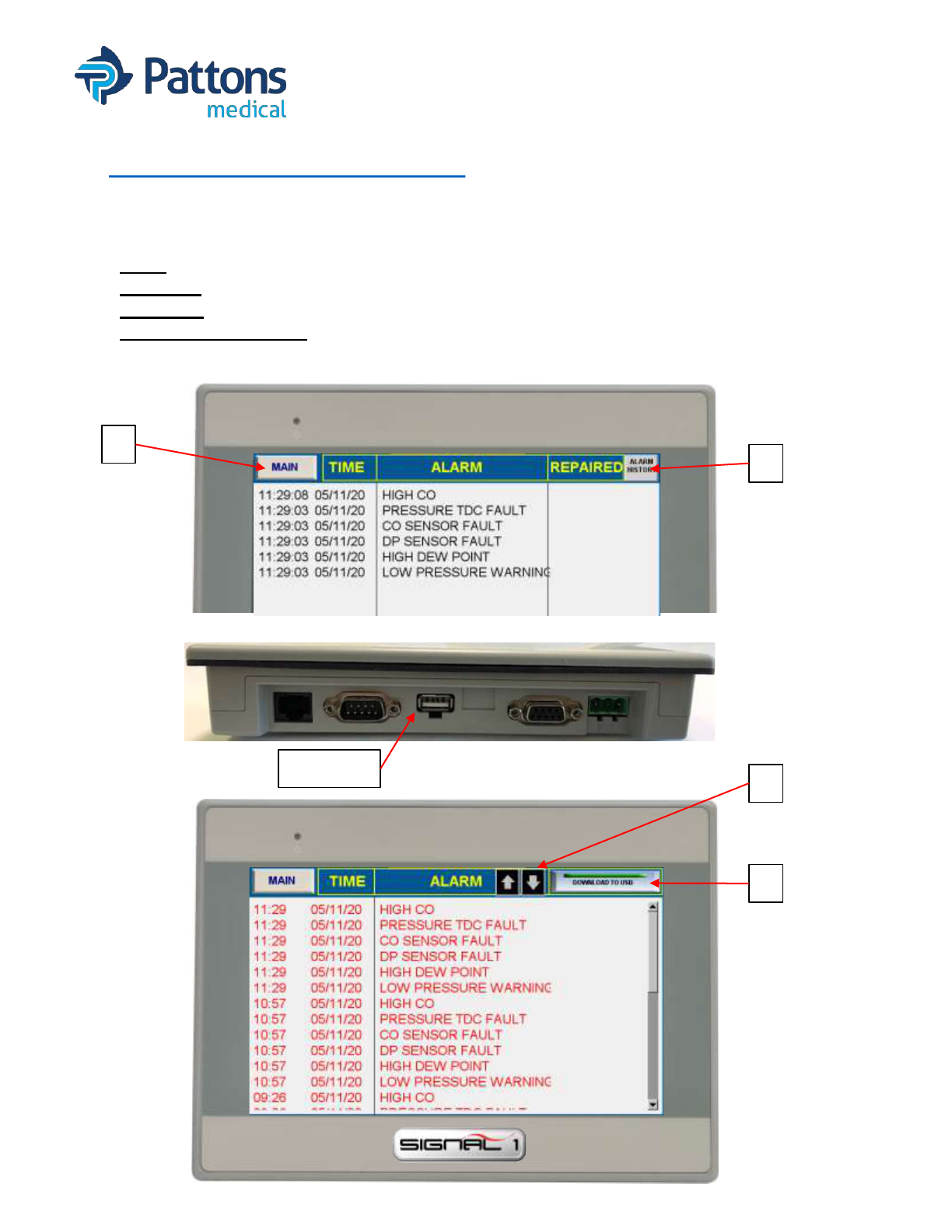
• ALARM HISTORY Screen
The Alarm History screen provides an overview off the last alarms that have been logged. It
provides the time and date the alarm triggered, the type of alarm, and the time the alarm was
repaired or cleared.
1. MAIN: Takes you back to the main screen.
2. HISTORY: Takes you to the Alarm History page.
3. ARROWS: Allows you to scroll thru days of alarms.
4. DOWNLOAD TO USB: Allows you to download all alarms to a USB memory device.
1
2
4
3
USB port
• T 704 529 5442 W pattonsmedical.com
Page 13
DOC# Manual_Signal1 Revision 11/1/2021
SIGNAL 1 with SYSTEM HEALTH
OPERATING INSTRUCTIONS
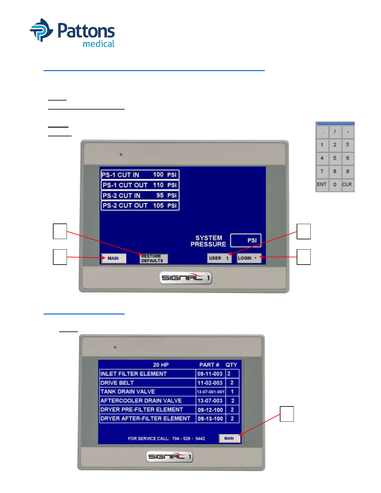
• PRESSURE/VACUUM SETTING Screen
The Pressure or Vacuum Setting screen allows you to customize the settings for the system.
It also allows you to return these values back to the default values.
1. MAIN: Takes you back to the main screen.
2. RESTORE DEFAULTS: Returns pressure/vacuum settings to factory default. The USER
and LOGIN must be entered to activate the button.
3. USER: Enter to be able to restore defaults (2 then ENT)
4. LOGIN: Enter to be able to restore defaults (327 then ENT)
102
1
2
3
4
• PARTS Screen
The Parts menu provides a list of common service item part numbers to the equipment.
1. MAIN: Takes you back to the main screen.
1

• T 704 529 5442 W pattonsmedical.com
Page 14
DOC# Manual_Signal1 Revision 11/1/2021
SIGNAL 1 with SYSTEM HEALTH
OPERATING INSTRUCTIONS
• SYSTEM DATA Screen
The System Data screen provides key information about the system that is helpful to the
service person and/or when calling for support.
1. MAIN: Takes you back to the main screen.
2. USER: Enter to be able to restore defaults (2 then ENT)
3. LOGIN: Enter to be able to make changes/access more menus (327 then ENT)
4. DATE and TIME: After login, touch the #’s and a pop-up screen will appear to change
5. COMMON ALARMS/SETUP: This button takes you to a screen that allows selection of
what conditions/alarms will activate the common alarm signal. This screen also allows the
user to select units and turn OFF horns for System Health warnings.
5. HIDDEN SERVICE BUTTONS: These buttons are for service and setup of the controller.
1. ACCESS: USER: 4; LOGIN: 396
2. LAN SETTINGS: To change the IP addresses for PLC interface and MODBUS data.
3. SYSTEM SETUP: For initial setup of HMI.
4. CHANGE PARAMETERS: To adjust the service intervals; change DP units; change
date and time
2
1
5
2
3
3
4
1
4

• T 704 529 5442 W pattonsmedical.com
Page 15
DOC# Manual_Signal1 Revision 11/1/2021
SIGNAL 1 with SYSTEM HEALTH
OPERATING INSTRUCTIONS
• COMMON ALARM Screen
The common alarm screen allows the operator to select which alarms will trigger the common
alarm output signal. When lighted, the alarm is activated to trigger the common alarm output.
*NOTE: Alarms are dependent on type of system. Not all alarms may be present on all systems.
1. MAIN: Takes you back to the main screen.
2. LAG ALARM: Alarms when the pump in reserve turns on. There is a separate alarm as well.
3. HIGH TEMP: Alarms when the high temperature switches close (discharge-air; exhaust-vac)
4. MOTOR OVERLOAD: Alarms when the overload relay trips. Must manually reset.
5. PUMP FAILED TO RUN: Alarms when the module does not start. Find reason and repair.
6. HIGH INLET FAULT (scroll only): Alarms when a vacuum is sensed at the inlet. The isolation
valve is closed or something is blocking the intake. Equipment protection fault.
7. HIGH DEW POINT: Alarms when high dewpoint sensed. There is a separate alarm as well.
8. DP SENSOR RECAL: Service alarm for when recalibration is due on the dewpoint sensor.
9. DRYER FILTERS DUE: Service alarm when particulate filters reach defined time limit.
10.DRYER DESICCANT DUE: Service alarm when desiccant reaches defined time limit.
11.SYSTEM HEALTH: Sends alarm signal when any system health reaches defined setting.
12.INLET FILTER DUE: Service alarm when inlet filters reach defined time limit.
13.CHECK BELT TENSION: Service alarm when belt reaches defined time limit.
14.500 HR TIP SEAL WARNING: Service alarm to notify the scroll pump is nearing rebuilt time.
15.TIP SEAL REPLACE DUE: Service alarm to notify the scroll pump needs to be rebuilt based
on a defined time limit.
16.HIGH CO: Alarms when high CO is sensed. There is a separate alarm as well.
17.CO SENSOR RECAL: Service alarm for when recalibration is due on the CO sensor.
18.SYSTEM UNITS: Allows the user to change the units for temperature and pressure readings.
19.SYSTEM HEALTH HORN SETUP: Allows the user to turn off horn alarms for system health
faults.
For standard vacuum systems, the RUN TIME selection is also available to select on this screen.
1
18
19

• T 704 529 5442 W pattonsmedical.com
Page 16
DOC# Manual_Signal1 Revision 11/1/2021
SIGNAL 1 with SYSTEM HEALTH
OPERATING INSTRUCTIONS
• SERVICE INTERVALS (Change Parameters) Screen
The Service Intervals screen allows the operator to adjust the standard service times of
serviceable items. The current setting is shown in the boxes beside the description.
1. MAIN: Takes you back to the main screen.
2. USER: Allows user to login and adjust settings on the screen (4 then ENT)
3. LOGIN: Allows user to login and adjust settings on the screen (396 then ENT)
4. DEW POINT CHANGE C to F (air only): Allows user to change dewpoint display between °C
and °F.
5. COMMON ALARM SCREEN: Take user to common alarm screen.
6. INLET FILTER: Standard replacement is 1/year.
7. BELT CHECK/REPLACE (air only): Standard check is every 6 months.
8. DRYER FILTERS (air only): Standard replacement is every 5 years.
9. DRYER DESICCANT (air only): Standard replacement is 1/year.
10.DEWPOINT CALIBRATION (air only): Standard calibration is every 2 years.
11.CO SENSOR CALIBRATION (air only): Standard calibration is 1/year.
12.OIL AND FILTER (vacuum only): Standard replacement is shown (varies based on type of
vacuum).
1
5
2
3
4
• T 704 529 5442 W pattonsmedical.com
Page 17
DOC# Manual_Signal1 Revision 11/1/2021
SIGNAL 1 with SYSTEM HEALTH
OPERATING INSTRUCTIONS
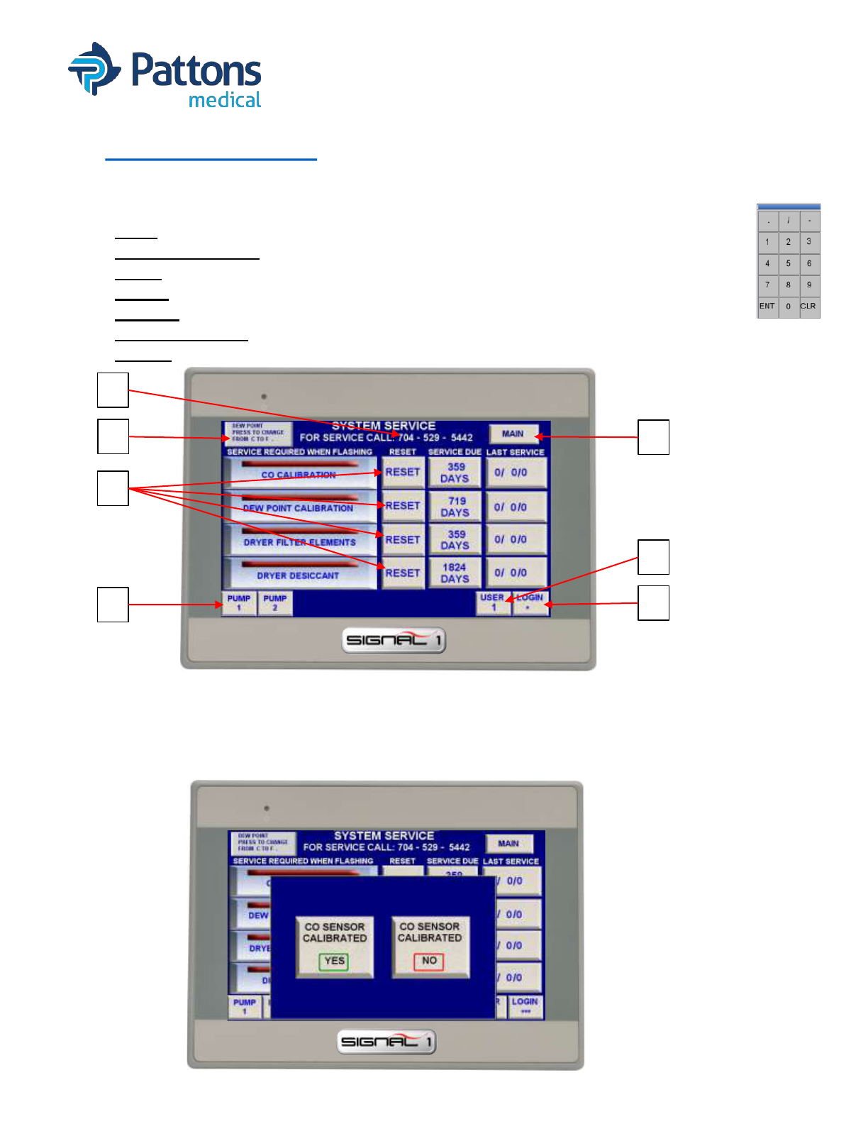
• SERVICE Screen
The Service screen provides information on when the service function was last performed and
how many days or hours until service is due again. When service is due, the tag on the left
will flash as notification and the Service Due button will be illuminated on the main page.
1. MAIN: Takes you back to the main screen.
2. DEWPOINT C to F: Allows user to change units for the dewpoint reading.
3. USER: Allows user to reset service time (4 then ENT)
4. LOGIN: Allows user to reset service time (396 then ENT)
5. PUMP X: Opens the service screen for a particular module.
6. Phone # Change: When logged in, the phone # can be touched and changed per section.
7. RESET: Records the date of reset and resets the hours/days until next service.
1
2
3
4
6
5
7
• RESET SCREEN (same layout for all service resets)
The reset screen allow the operator to reset the service performed. When selecting YES, the
date will be recorded and displayed and the service due timer will be reset to the set value.
Selecting NO will exit the screen and nothing is recorded.
• T 704 529 5442 W pattonsmedical.com
Page 18
DOC# Manual_Signal1 Revision 11/1/2021
SIGNAL 1 with SYSTEM HEALTH
OPERATING INSTRUCTIONS
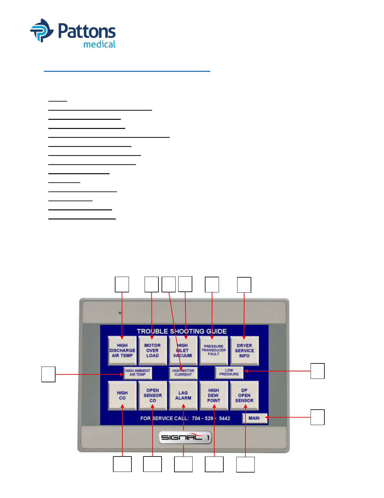
• TROUBLESHOOTING Screen
The Pressure or Vacuum Setting screen allows you to customize the settings for the system. It
also allows you to return these values back to the default values.
1. MAIN: Takes you back to the main screen.
2. HIGH DISCHARGE AIR TEMP: Opens a pop-up window with possible reasons for alarm.
3. MOTOR OVERLOAD: Opens a pop-up window with possible reasons for alarm.
4. HIGH INLET VACUUM (scroll only): Opens a pop-up window with possible reasons for alarm.
5. PRESSURE TRANSDUCER FAULT: Opens a pop-up window with possible reasons for fault.
6. DRYER SERVICE INFO (air only): Opens a pop-up window with possible reasons for alarm.
7. HIGH AMBIENT AIR TEMP: Opens a pop-up window with possible reasons for alarm.
8. HIGH MOTOR CURRENT: Opens a pop-up window with possible reasons for alarm.
9. LOW PRESSURE: Opens a pop-up window with possible reasons for alarm.
10.HIGH CO: Opens a pop-up window with possible reasons for alarm.
11.CO OPEN SENSOR: Opens a pop-up window with possible reasons for fault.
12.LAG ALARM: Opens a pop-up window with possible reasons for alarm.
13.HIGH DEW POINT: Opens a pop-up window with possible reasons for alarm.
14.DP OPEN SENSOR: Opens a pop-up window with possible reasons for fault.
32
1
6
5
4
7
9
8
1110
14
1312
• T 704 529 5442 W pattonsmedical.com
Page 19
DOC# Manual_Signal1 Revision 11/1/2021
SIGNAL 1 with SYSTEM HEALTH
OPERATING INSTRUCTIONS
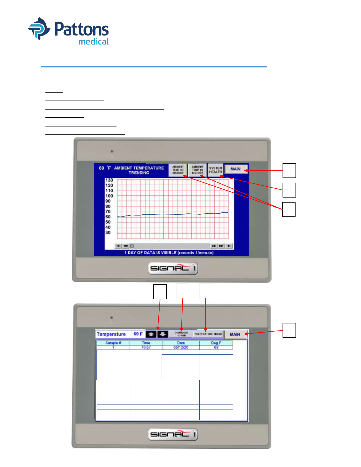
• AMBIENT TEMPERATURE TREND Screen
The ambient temp trend screen and data screens allow the operator to see the temperature
history to assist in correlating to any problems or issues that have been seen.
1. MAIN: Takes you back to the main screen.
2. SYSTEM HEALTH: Takes you back to the system health screen.
3. AMBIENT TEMP (F) or (C) HISTORY: Opens screen with readings in °F or °C for export.
4. “ARROWS”: Allows scrolling thru readings.
5. DOWNLOAD TO USB: Allows user to export data readings to USB drive.
6. TEMPERATURE TREND: Takes user back to Temperature trending graph page.
2 10:56
05/12/20
69
3 10:55
05/12/20
68
4 10:54
05/12/20
68
5 10:53
05/12/20
68
6 10:52
05/12/20
69
8 10:51
05/12/20
68
9 10:50
05/12/20
68
10 10:49
05/12/20
67
11 10:48
05/12/20
67
12 10:47
05/12/20
67
13 10:46
05/12/20
68
14 10:45
05/12/20
68
15 10:44
05/12/20
68
16 10:43
05/12/20
68
4
6
1
5
1
2
3

• T 704 529 5442 W pattonsmedical.com
Page 20
DOC# Manual_Signal1 Revision 11/1/2021
SIGNAL 1 with SYSTEM HEALTH
OPERATING INSTRUCTIONS
• AMPERAGE TREND Screen
The amperage trend screen allows the operator to see the graph and data points of the amps
being drawn by each motor to see if there is a trend that may foreshadow a problem.
1. MAIN: Takes you back to the main screen.
2. SYSTEM HEALTH: Takes you back to the system health screen.
3. MOTOR X DATA: Opens screen with amp readings for that motor for export.
4. “ARROWS”: Allows scrolling thru readings.
5. DOWNLOAD TO USB: Allows user to export data readings to USB drive.
6. CURRENT TREND: Takes user back to Amperage trending graph page.
4
6
1
5
1
2
3

• T 704 529 5442 W pattonsmedical.com
Page 21
DOC# Manual_Signal1 Revision 11/1/2021
SIGNAL 1 with SYSTEM HEALTH
OPERATING INSTRUCTIONS
• PRESSURE TREND Screen
The pressure trend screen allows the operator to view the graph and data points for the
pressure history and export the data if needed.
1. MAIN: Takes you back to the main screen.
2. MENU: Takes you back to the menu screen.
3. SYSTEM PSI or BAR HISTORY: Opens screen with readings for that motor for export.
4. “ARROWS”: Allows scrolling thru readings.
5. DOWNLOAD TO USB: Allows user to export data readings to USB drive.
6. PSI TREND: Takes user back to PSI trending graph page.
4
6
1
5
1
2
3
100
102
102
103
104
105
104
102
103
101
101
100
99
98
98
98
102

• T 704 529 5442 W pattonsmedical.com
Page 22
DOC# Manual_Signal1 Revision 11/1/2021
SIGNAL 1 with SYSTEM HEALTH
OPERATING INSTRUCTIONS
• # PUMPS RUNNING TREND Screen
The pumps running trend screen allows the operator to see how many pumps are running is
graph and data point form and export the data if needed.
1. MAIN: Takes you back to the main screen.
2. MENU: Takes you back to the menu screen.
3. PUMPS RUNNING HISTORY: Opens screen with readings for export.
4. “ARROWS”: Allows scrolling thru readings.
5. DOWNLOAD TO USB: Allows user to export data readings to USB drive.
6. PUMPS RUNNING: Takes user back to Pumps running trending graph page.
4
6
1
5
1
2
3

• T 704 529 5442 W pattonsmedical.com
Page 23
DOC# Manual_Signal1 Revision 11/1/2021
SIGNAL 1 with SYSTEM HEALTH
OPERATING INSTRUCTIONS
• PUMP CYCLE TREND Screen
The pumps cycle trend screen allows the operator to see when a pump is running and get
graph and data points and export the data if needed.
1. MAIN: Takes you back to the main screen.
2. SYSTEM HEALTH: Takes you back to the System Health screen.
3. MOTOR X DATA: Takes you to screen with data points for individual pumps.
4. “ARROWS”: Allows scrolling thru readings.
5. DOWNLOAD TO USB: Allows user to export data readings to USB drive.
6. CYCLE TREND: Takes user back to Cycle trending graph page.
4
6
1
5
1
2
3
• T 704 529 5442 W pattonsmedical.com
Page 24
DOC# Manual_Signal1 Revision 11/1/2021
SIGNAL 1 with SYSTEM HEALTH
OPERATING INSTRUCTIONS
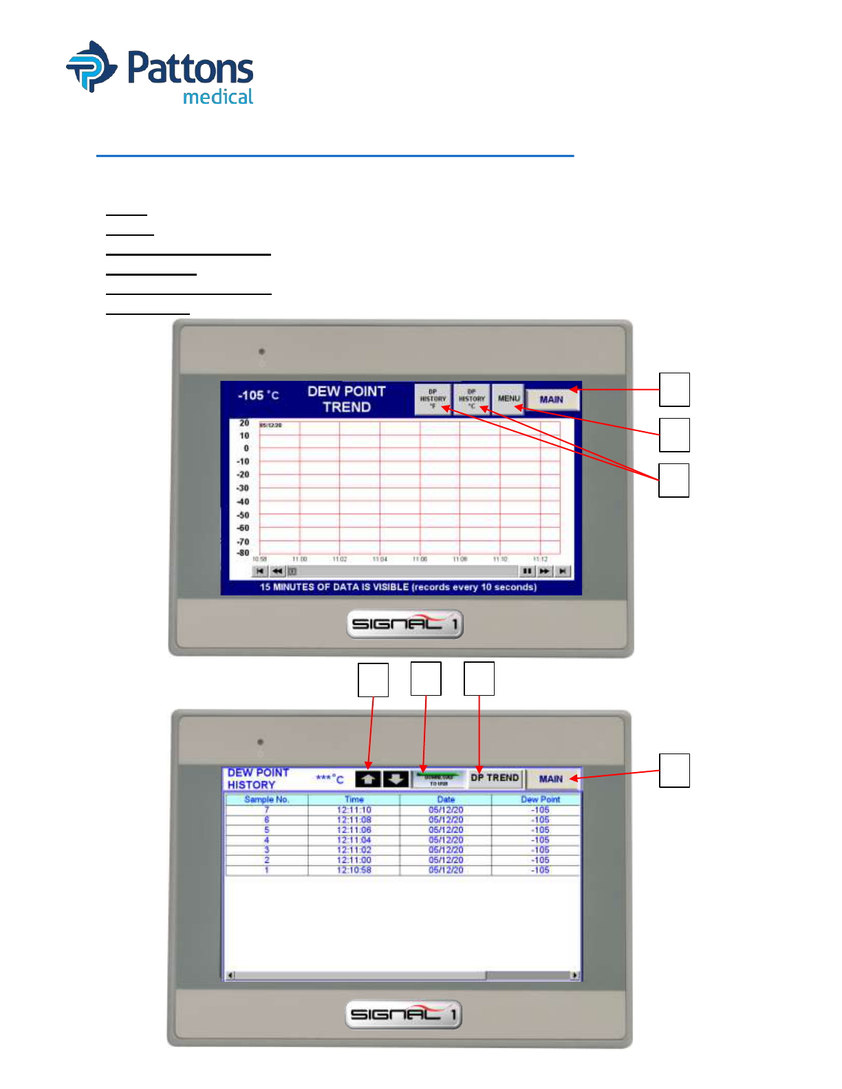
• DEW POINT TREND Screen (air only)
The dew point trend screen allows the operator to see the dew point and get graph and data
points and export the data if needed.
1. MAIN: Takes you back to the main screen.
2. MENU: Takes you back to the menu screen.
3. DP HISTORY °F or °C: Takes you to screen with data points for dewpoint in °F or °C.
4. “ARROWS”: Allows scrolling thru readings.
5. DOWNLOAD TO USB: Allows user to export data readings to USB drive.
6. DP TREND: Takes user back to Cycle trending graph page.
4
6
1
5
1
2
3
• T 704 529 5442 W pattonsmedical.com
Page 25
DOC# Manual_Signal1 Revision 11/1/2021
SIGNAL 1 with SYSTEM HEALTH
OPERATING INSTRUCTIONS
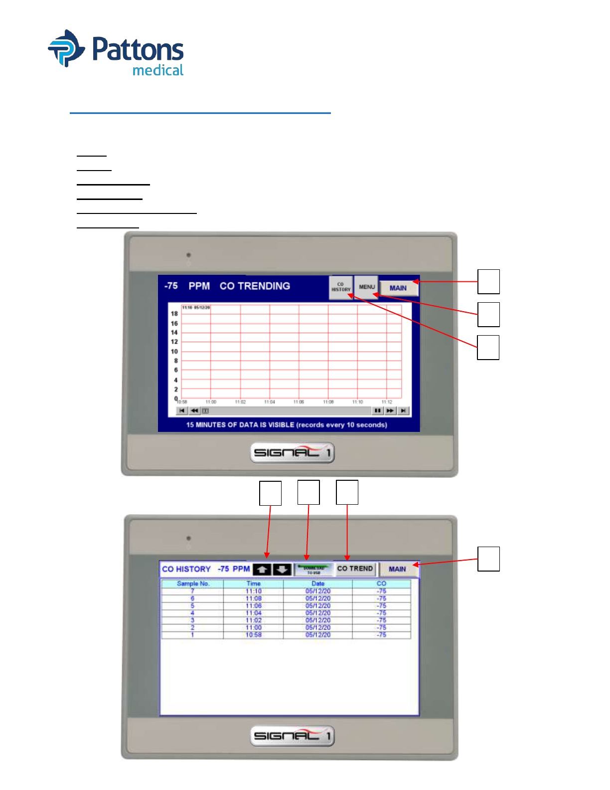
• CO TREND Screen (air only)
The dew point trend screen allows the operator to see the dew point and get graph and data
points and export the data if needed.
1. MAIN: Takes you back to the main screen.
2. MENU: Takes you back to the menu screen.
3. CO HISTORY: Takes you to screen with data points for CO.
4. “ARROWS”: Allows scrolling thru readings.
5. DOWNLOAD TO USB: Allows user to export data readings to USB drive.
6. CO TREND: Takes user back to Cycle trending graph page.
4
6
1
5
1
2
3

• T 704 529 5442 W pattonsmedical.com
Page 26
DOC# Manual_Signal1 Revision 11/1/2021
SIGNAL 1 with SYSTEM HEALTH
OPERATING INSTRUCTIONS
• LAN SETTINGS screen
The LAN settings screen allows the operator to change the IP address of the HMI, PLC, and
output MODBUS. Additional network parameters can also be changed.
1. MAIN: Takes you back to the main screen.
2. USER: Allows operator to log in to make changes (4 then ENT).
3. LOGIN: Allows operator to log in to make changes (396 then ENT).
4. PORT: Allows operator to change the port number of the HMI. Consult IT before changing.
5. LAN 1: IP address of the HMI. Consult IT before changing.
6. MAC 1: MAC address of HMI. Consult IT before changing.
7. SHOW LAN SETTING TAB: This brings up HMI login screen. Adjustments to IP address,
time, date, and other HMI settings can be made thru this login.
8. RESET: Press after in block after changing the IP address of the HMI, PLC, or Modbus.
9. PLC IP ADDRESS: Address where HMI is looking for PLC.
10.PLC PORT: Port location of PLC IP Address.
11.MODBUS IP ADDRESS: Address where HMI is sending MODBUS packets.
12.MODBUS PORT: Port location where Modbus packets are being sent.
13.MODBUS STATION No: Station number of Modbus device.
14.MODBUS OFF: Turns off Modbus output.
15.PLC IP ADDRESS: This function requires a special login. Contact Pattons Medical.
• Top address it he current PLC IP address
• Lower address is the new address to be saved. New address must be enter in HEX.
• i.e.: If IP address needs to be 192.168.1.20, the you would enter
1
st
block: C0A8 and 2
nd
block: 0114
16.ALT IP USAGE: Select this button to make the new PLC IP address active in the PLC.
Then the PLC and HMI must be rebooted.
15
16
HEX entry
1
6
5
8
2
3
4
87
9
10
11
12
14
13

• T 704 529 5442 W pattonsmedical.com
Page 27
DOC# Manual_Signal1 Revision 11/1/2021
SIGNAL 1 with SYSTEM HEALTH
OPERATING INSTRUCTIONS
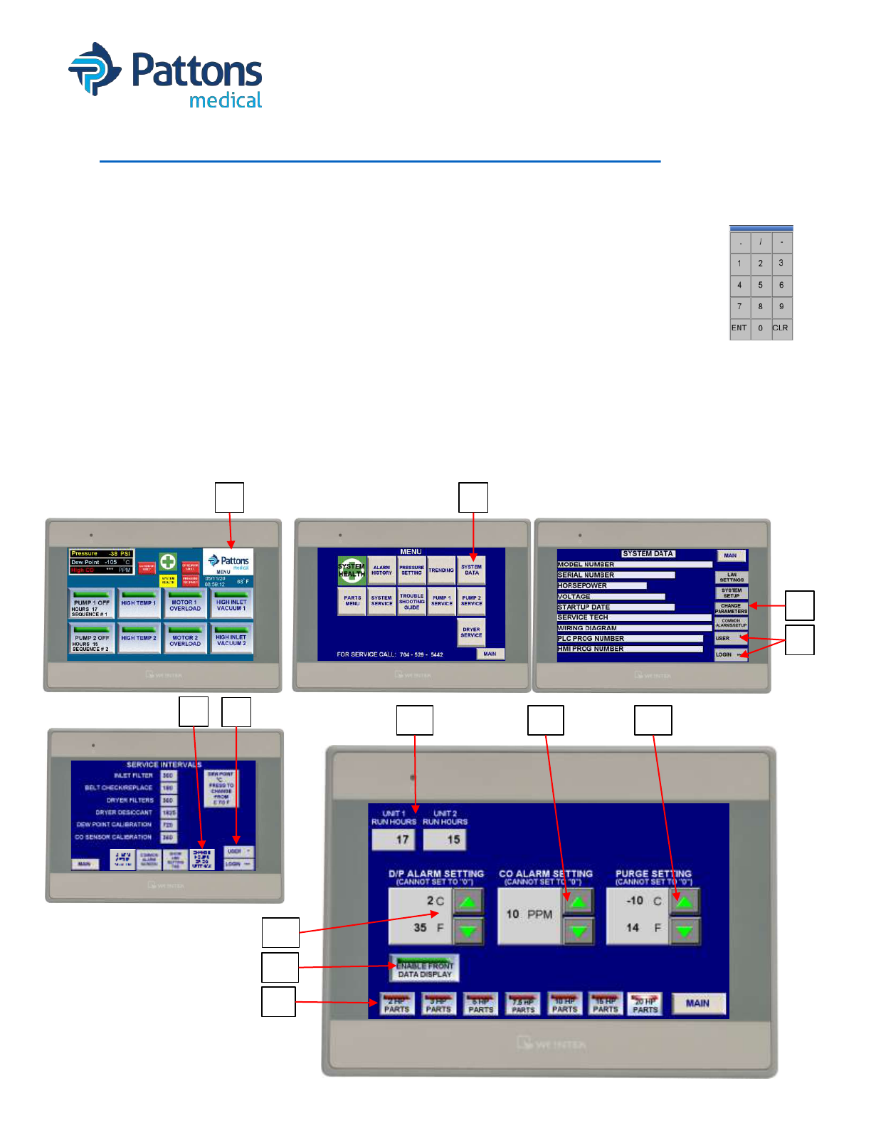
• HMI SETTING TAB
The HMI Setting tab allow the operator to make changes to HMI parameters. The 2 most
common changes are 1) IP address and 2) date and time. There are several others too.
1. Go to MENU screen
2. Select SYSTEM DATA tab
3. Enter USER 4, then ENT
4. Enter LOGIN 396, then ENT
5. Select CHANGE PARAMETERS button
6. Enter USER 4; LOGIN 396
7. Select SHOW HMI SETTING TAB
8. A pop-up KEYBOARD will appear, then a PASSWORD pop-up screen.
9. Once PASSWORD screen appears, enter 111111 for password and hit OK (may auto exit)
10.SYSTEM SETTINGS pop-up screen will appear.
11.At this point, changes can be made to any system setting. Select APPLY to save. Select
OK or CANCEL to exit.
1 2
4
5
3
6 7 9 8
10
IP
addr
Date
Time
• T 704 529 5442 W pattonsmedical.com
Page 28
DOC# Manual_Signal1 Revision 11/1/2021
SIGNAL 1 with SYSTEM HEALTH
OPERATING INSTRUCTIONS
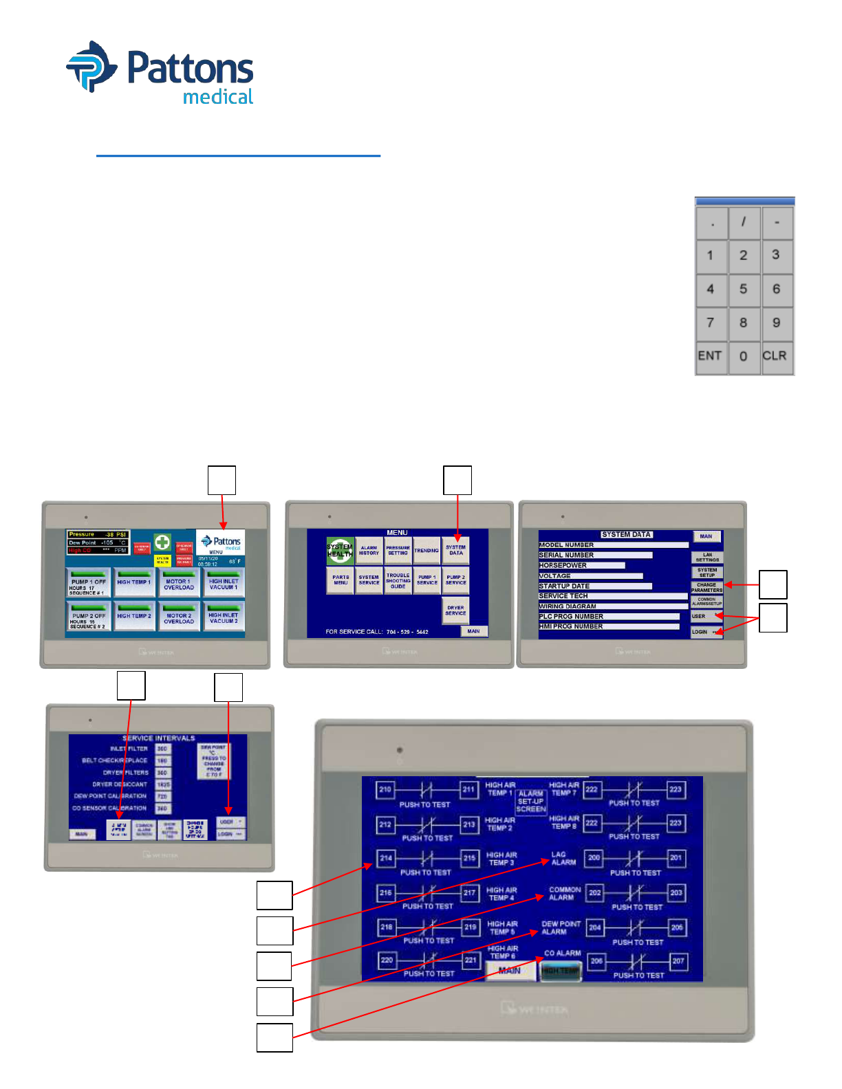
• CHANGE HOURS DP/CO SETTINGS screen
This screen has several adjustments that can be made for specific reasons by service only.
• Allows the service person to adjust the hours on each pump when PLC replaced.
• Allows the service person to adjust the DP, CO, and purge settings. The DP and CO are
default set to the NFPA 99 requirements. Purge is set to avoid a DP alarm.
1. Menu
2. System Data (User 4; Login 396)
3. Change Parameters (Login for Trained Service Personnel ONLY)
4. Change Hours DP/CO Settings
5. Once you have reached this screen, the
a) HOURS of each module can be changed (should only be done if PLC replaced)
b) DP ALARM SETTING can be changed (2°C is NFPA alarm setting)
c) CO ALARM SETTING can be changed (10 PPM is NFPA alarm setting)
d) PURGE SETTING can be changed
e) Front additional data can be displayed (mostly for VNC connection)
f) Parts list can be selected
1 2
3
2
3
5a
4
5e
5d5c
5b
5f
• T 704 529 5442 W pattonsmedical.com
Page 29
DOC# Manual_Signal1 Revision 11/1/2021
SIGNAL 1 with SYSTEM HEALTH
OPERATING INSTRUCTIONS
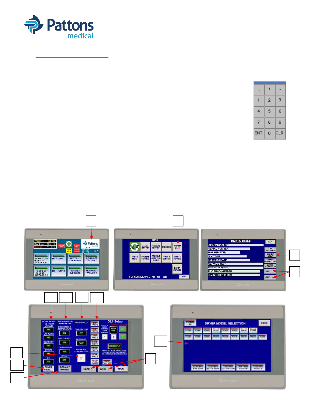
• ALARM SETUP screen
This screen allows the service person and certifier to trigger alarms for testing the system.
1. Menu
2. System Data (User 4; Login 396)
3. Change Parameters (Login for Trained Service Personnel ONLY)
4. Alarm Setup Screen
5. Once you have reached this screen, the
a) HIGH AIR TEMP for each module can be selected to see how to test
b) LAG ALARM can be triggered for test
c) COMMON ALARM can be triggered for test
d) DEW POINT ALARM can be triggered for test
e) CO ALARM can be triggered for test
1 2
3
2
3
4
5a
5b
5c
5d
5e
• T 704 529 5442 W pattonsmedical.com
Page 30
DOC# Manual_Signal1 Revision 11/1/2021
SIGNAL 1 with SYSTEM HEALTH
OPERATING INSTRUCTIONS
• SYSTEM SETUP
The HMI is designed to be modular with lots of options that can be turned OFF if not wanted.
This screen allows the assembler or service person to customize each unit to exactly what the
customer needs. This screen also allows for the setup of parts list, quantities, and setup of the
XCOM module in the overloads to read amps.
1. Menu
2. System Data (Login for Trained Service Personnel ONLY)
3. System Setup (Login for Trained Service Personnel ONLY)
4. Once you have reached this screen, there are multiple sections to review.
a) ALARM SETUP:
• HIGH INLET VACUUM (scroll only): ON if remote intake piping.
• LAG ALARM: ON for Medical; optional for all other applications
• DEW POINT: OFF if no dew point sensor installed on package
• DRYERS: OFF if no dryers installed on package
• CO: OFF if no CO sensor is installed on package
b) SYSTEM HEALTH HORN SETUP: horn alarms can be individually turned off
c) SYSTEM UNITS: can select units for temperature and pressure/vacuum
d) PARTS: select which parts list to show; may be extra selection for some models
e) DEFAULT PHONE #: enters the default Pattons Medical phone # on screens
f) ENTER # OF COMPRESSORS: defines quantities of parts for package & unit setup
g) DRYER SELECT: allows assembler to select dryers installed so service parts info is
correct on the parts screen. Many options due to pressure, Lag, other.
1 2
3
2
3
4a 4b
4c
4d
4g
4e
4f
4g

• T 704 529 5442 W pattonsmedical.com
Page 31
DOC# Manual_Signal1 Revision 11/1/2021
SIGNAL 1 with SYSTEM HEALTH
OPERATING INSTRUCTIONS
• SYSTEM SETUP (continued)
One of the features of System Health is the reading of amps thru the overload. The overloads
ID number has to be set-up when installed. All ID’s are 1 by default. If the overload and
XCOM are replaced, the address will have to be setup with this procedure.
1. Login on this screen: Login for Trained Service Personnel ONLY
2. Turn OFF XCOM RUN to XCOM SETUP.
3. Current address should be 1 (and this is default in the box on left)
4. Use “arrows” to define the number of the newly installed XCOM/overload (module 4 is #4)
5. Unplug all cables from XCOM modules except one being programmed.
6. Press XCOM LOAD button; button should light up, then turn OFF; this means a good write
7. Plug up all XCOM cables
8. Reboot PLC, HMI, and XCOMS (pull F15)
9. To check if working, the RS-485 RD & SD lights should be solid or very fast blink. If PLC
ERROR light comes ON and lights are not solid, then there is a communication/read error.
1
2
3 46
9 (RD/SD)
9 (ERROR)

• T 704 529 5442 W pattonsmedical.com
Page 32
DOC# Manual_Signal1 Revision 11/1/2021
SIGNAL 1 with SYSTEM HEALTH
OPERATING INSTRUCTIONS
• WRITE PLC PROGRAM from SDHC CARD
To update the PLC program, you will need a
• blank SDHC card
• laptop (or computer) with an SDHC card slot
• Program on computer to unzip the emailed program file
1. Save zipped PLC program to computer
2. Unzip the file and save the folder of files ($MELPRJ$) to the SDHC card
3. Notify appropriate people that Source Equipment alarms at the Master panel are going to
alarm
4. Turn enough pumps to HAND to handle the load
5. Turn PLC switch to STOP (middle) position
6. Install SDHC card into SD card slot on PLC
7. Push down and hold (3 seconds) STOP switch in RESET position (this loads new program)
• CARD LED will blink a few times and then go solid (when blinking, it is loading program)
6. Wait 30 seconds, then push and hold SD CARD OFF button until CARD light if OFF
7. When CARD light is off, push SD card in to EJECT (remove card)
8. Push down STOP switch again for 3 seconds to RESET the system
9. Then push up STOP switch to RUN position to start PLC.
10.Verify all alarms are correct and that PLC issue is not corrected
11.If good, notify appropriate people that you are done with source equipment repair.
5 (CARD LED)
4 (SDHC CARD slot)
6 (SD CARD OFF)
3/5/8/9 (STOP switch)
• T 704 529 5442 W pattonsmedical.com
Page 33
DOC# Manual_Signal1 Revision 11/1/2021
SIGNAL 1 with SYSTEM HEALTH
OPERATING INSTRUCTIONS
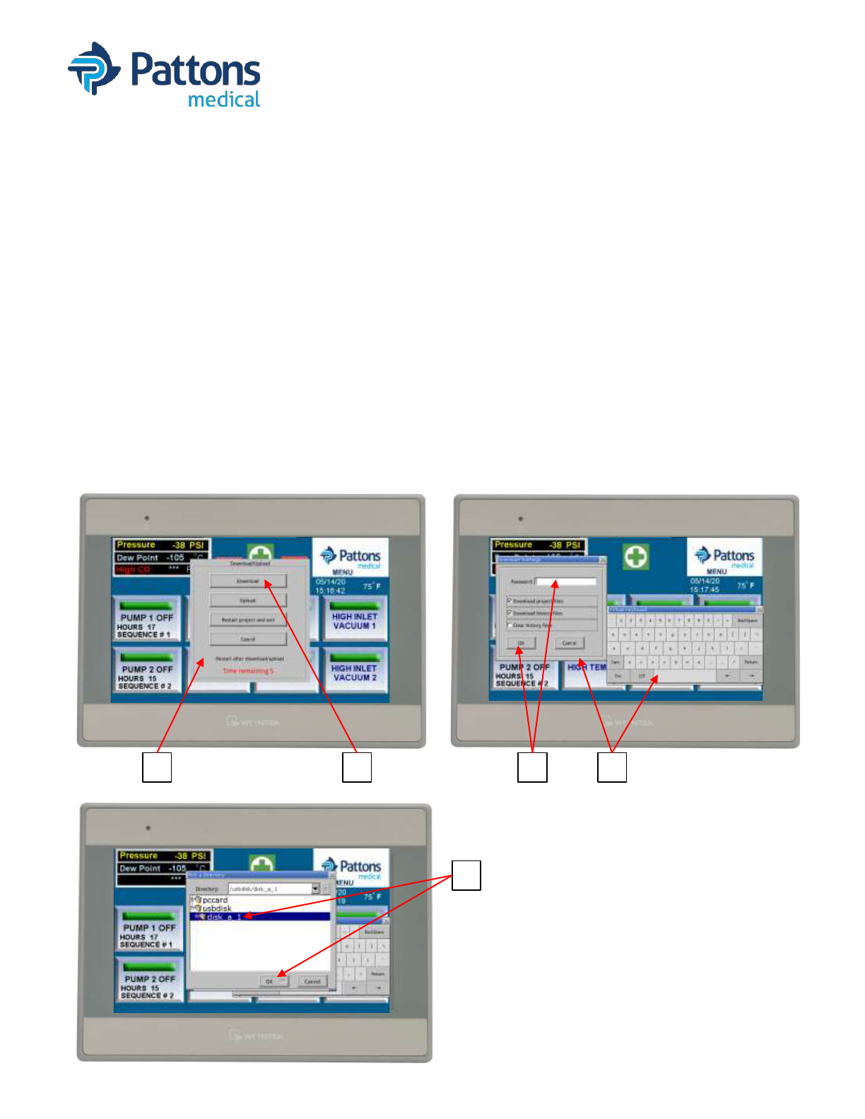
• WRITE HMI PROGRAM from USB stick
To update the USB program, you will need a
• blank USB memory stick
• laptop (or computer) with an USB connection
• Program on computer to unzip the emailed program file
1. Save zipped HMI program to computer
2. Unzip the file and save the folder of files (mt8000ie) to the USB stick
3. Install USB stick into USB slot on back bottom side of HMI
4. DOWNLOAD screen will appear on the HMI
5. Press the DOWNLOAD button on the screen
6. A keyboard and Password screen will appear
7. Enter 111111 (6x 1’s) and press OK (may auto OK)
8. Select usbdisk, then select/highlight “disk_a_1”
9. Press OK and program will start to download
10.When the initial screen reappears, the USB drive can be removed
4 5 67
8

• T 704 529 5442 W pattonsmedical.com
Page 34
DOC# Manual_Signal1 Revision 11/1/2021
SIGNAL 1 with SYSTEM HEALTH
OPERATING INSTRUCTIONS
• Warranty
Patton’s Medical Systems Warranty
Patton’s Medical warrants that all systems to be free of defects in material and workmanship under normal use for a
period of twenty-four months from start-up, not to exceed thirty months from date of shipment. This warranty covers
all necessary parts used in repair as well as all reasonable labor expense. Normal consumable parts required for
routine scheduled maintenance (such as filters) are not covered under this warranty.
This warranty does not apply to products that are damaged by external causes, or are improperly warehoused, used,
installed, serviced, misapplied or maintained by the customer. The sole liability for Patton’s Medical under this
warranty is limited to repairing, replacing, or crediting, at its election, any such products provided t hat:
• Patton’s Medical is notified promptly wit hin the warranty period above of any warranty claim.
• The exa mination of such items by an authorized representative of Patton’s Medical will disclose to their
reasonable satisfaction that claimed products defect has not been caused by misuse, neglect, improper handling,
installation, repair, alteration, or accidents.
• Patton’s Medical requires that systems above 5 Hp simplex be commissioned by an authorized Patton’s
Medical distributor and requires a start-up report to be filed within 30 days of equipment start-up. Failure to
submit a start-up repor t to Patton’s Medical will void the warranty.
• Replacement Parts including pumps and motors carry a limited warranty based upon manufacturer specific
terms. Parts carry a 90 day warranty unless the manufacturer’s stated warranty is different. Labor for these
warranties is not included or implied and is at the sole discretion of Patton’s Medical.
• Retrofit Control Panels carry a 12 month warranty from date of shipment.
• Simplex units 5Hp and below as well as r etrofit dryer packages do not include factory assisted start-up in t heir
base price unless specifically noted otherwise.
• Extended warranty is offered and will be noted in the quote.
Product modification performed by the customer without prior written approval by Patton’s Medical will invalidate
the above warranty.
This warranty is given in lieu of all other warranties, expressed or implied, including implied warranties of
fitness for a particular purpose and merchantability. In no event shall Patton’s Medical be liable for damages
in excess of the value of the defective product or part, nor shall Patton’s Medical be liable for any indirect,
special or consequential damages, loss of profits of any kind, or for loss of use of the products.
Patton’s Medical shall not be liable to the customer for any claims, loss of damage of any kind whatsoever arising
from the nonperformance of Patton’s Medical of any part of this agreement occasioned by acts of God, fire, war,
labor difficulties, governmental regulations, or action of government. Patton’s Medical shall not be liable to the
customer for any other cause, whether of a similar or dissimilar nature beyond its reasonable control.

• T 704 529 5442 W pattonsmedical.com
Page 35
DOC# Manual_Signal1 Revision 11/1/2021
SIGNAL 1 with SYSTEM HEALTH
OPERATING INSTRUCTIONS
4610 Entrance Drive, Suite H
Charlotte, NC 28273
704-529-5442
www.pattonsmedical.com
